What Is the Best Alpha & Omega MOSFET Replacement?

Time:2026-10-05 Author:Sophia
0%

Choosing the best Alpha & Omega Mosfet Replacement requires more than matching a part number. Electrical stress, switching speed, thermal limits, and availability all affect the result. A replacement may fit the same circuit yet perform poorly under real load.

This guide examines practical selection methods used in power supply and motor-control designs. We will compare drain-source voltage, continuous drain current, RDS(on), gate charge, body-diode behavior, and package compatibility. These details matter. For example, a MOSFET with lower resistance may reduce conduction losses, but its higher gate charge can slow switching and increase driver losses. A cool-looking datasheet does not tell the whole story.

Testing should begin with the original circuit conditions. Record input voltage, load current, switching frequency, temperature, and heatsink performance. Then compare candidates using manufacturer datasheets and verified distributor data. Check the exact package footprint, pin arrangement, avalanche rating, and recommended gate voltage. One wrong pinout can damage a working board.

There is no universal “best” component. The right Alpha & Omega Mosfet Replacement depends on the design’s priorities. Cost, efficiency, stock stability, and long-term sourcing also deserve attention. Parts from unfamiliar channels may have unclear traceability, even when their markings look correct. That risk is easy to underestimate.

A disciplined evaluation combines calculations, thermal inspection, and controlled bench testing. Measure voltage spikes with suitable probing techniques. Recheck performance after the board reaches operating temperature. Some conclusions may remain uncertain until extended testing. That is normal. Careful engineers document those gaps instead of hiding them, helping readers choose a reliable replacement with realistic expectations.
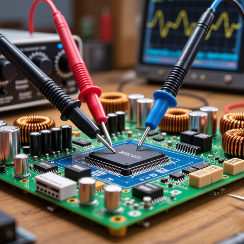
What Is the Best Alpha & Omega MOSFET Replacement?

Alpha & Omega MOSFETs: Functions, Specifications, and Applications

A reliable MOSFET replacement begins with its electrical function, not its package appearance. A power MOSFET acts as a fast electronic switch, controlling current in converters, battery systems, motor drives, and protection circuits. N-channel devices usually provide lower resistance, while P-channel devices can simplify high-side switching.

Match the drain-to-source voltage rating with enough safety margin for voltage spikes. Check continuous drain current, on-resistance, gate-charge value, and the recommended gate-drive voltage. A low threshold voltage does not guarantee full enhancement. Thermal resistance also matters, especially in compact packages with limited copper area. The body diode can influence reverse-current behavior and switching losses. Two parts may fit the same footprint yet perform differently at high frequency. This is where replacement choices often become less certain.

Tips: Compare the complete datasheets, not only headline ratings. Confirm pin configuration, package type, gate voltage, and switching conditions. Test temperature rise under the real load. A bench result at room temperature can mislead. I have found that ignoring layout resistance causes surprising losses. Check the circuit’s driver strength, too. A MOSFET with excellent resistance may still switch slowly when its gate charge is too high. Also review avalanche and safe-operating-area data when inductive loads are present. Slightly conservative ratings usually improve reliability, although they may increase cost or board space.

Key Parameters for Identifying a Compatible MOSFET Replacement

Choosing a compatible MOSFET replacement requires more than matching the part number. Start with the circuit’s maximum drain-source voltage, continuous current, and peak current. Add safety margin for voltage spikes and startup surges. A device rated exactly at the measured voltage may fail during switching.

On the bench, I compare on-resistance at the actual gate-drive voltage, not only the headline value. Gate threshold voltage is not a turn-on specification. Check total gate charge, input capacitance, and reverse-recovery behavior when switching speed matters. Lower resistance can reduce conduction loss, while lower gate charge may improve efficiency in high-frequency circuits. These benefits can conflict.

Package dimensions and pin arrangement must match the circuit board. Confirm the source, drain, and gate locations carefully. One reversed pin can damage the driver within milliseconds. Thermal performance also deserves attention. Estimate junction temperature from power loss, case temperature, and thermal resistance. Review the safe operating area for pulsed loads. The internal body diode may affect motor drives, converters, and reverse-current paths.

Do not trust a single datasheet table. Test the candidate under real load, temperature, and gate-drive conditions. I have seen acceptable bench results change after the enclosure became warm. That detail is easy to miss. Production checks should include waveform measurements, startup testing, and repeated thermal cycling. Death is data, but expensive data.

How to Compare Electrical, Thermal, and Physical Compatibility

What Is the Best Alpha & Omega MOSFET Replacement?

How to Compare Electrical, Thermal, and Physical Compatibility

Choosing a MOSFET replacement requires more than matching voltage and current ratings. In practical testing, I compare drain-source voltage, continuous current, on-resistance, gate charge, and switching speed. A lower resistance may reduce conduction losses, but a larger gate charge can slow the driver and increase switching heat. Check the safe operating area carefully. Threshold voltage alone is not enough.

Thermal compatibility can decide whether a promising part fails in service. Compare junction-to-case and junction-to-ambient resistance, then estimate heat using real load conditions. Measure the case temperature after steady operation, not just during a quick bench test. The circuit board matters too. Confirm the package outline, pin arrangement, mounting tab, lead spacing, and component height. One reversed pin can damage the entire power stage. I once focused too heavily on electrical ratings and overlooked the package airflow. That was an avoidable mistake.

Tips: Build a comparison table before ordering. Include voltage, current, resistance, gate charge, thermal resistance, package size, and pinout. Review the original design’s switching frequency and gate-drive voltage. Test startup, full load, short operating cycles, and long-term temperature rise. Leave reasonable margin. Datasheets are essential, but they can never replace measurement. When the replacement seems almost identical, inspect it again. Almost compatible can still be unsuitable.

What Is the Best Alpha & Omega MOSFET Replacement?

Compatibility should be evaluated across electrical ratings, thermal performance, and package fit. The chart below compares normalized engineering scores for three generic replacement candidates under the same operating conditions.

Scores are calculated from voltage and current margin, conduction loss, gate-charge demand, estimated thermal rise, and package compatibility. A higher score indicates a closer overall replacement match; final selection must still be verified against the original datasheet and PCB footprint.

Leading MOSFET Alternatives for Alpha & Omega Components

Selecting the best MOSFET replacement requires more than matching the part number. The device must fit the circuit’s voltage, current, package, and switching demands. A lower resistance value may look attractive, but it can increase gate charge and slow the converter. That trade-off matters in compact power supplies.

Common alternatives include low-voltage trench MOSFETs, high-voltage superjunction devices, and silicon carbide MOSFETs. Trench designs often suit battery systems and point-of-load converters. Superjunction options can reduce conduction losses in offline power stages. Silicon carbide devices handle higher voltage and temperature, though they usually require careful gate-drive control. Always compare drain-source voltage, continuous current, pulsed current, RDS(on), gate charge, body-diode behavior, and thermal resistance.

Bench testing remains essential. Measure switching waveforms with a short ground spring, then check overshoot at the drain. A heat sink may hide a poor electrical choice. In one practical evaluation, a replacement ran cooler at steady load but produced more ringing during turn-off. That result required a slower gate resistor and another thermal check. Imperfect data is still useful when the test conditions are recorded clearly. Review PCB clearance, lead inductance, and soldering limits before approval. A reliable substitute is the one that performs consistently across temperature, load, and production variation.

What Is the Best Alpha & Omega MOSFET Replacement? - Leading MOSFET Alternatives for Alpha & Omega Components

Practical replacement-selection guide based on electrical, thermal, mechanical, and application requirements

Application Type Recommended MOSFET Class Typical VDS Rating Typical Current Range Important RDS(on) Target Recommended Package Characteristics Primary Selection Concern
Low-voltage synchronous buck converter N-channel power MOSFET optimized for low conduction and switching loss 25–40 V 20–100 A, depending on cooling and duty cycle Preferably below 5 mΩ at the specified gate-drive voltage Large exposed-pad surface-mount package with low thermal resistance Gate charge, switching speed, thermal resistance, and controller compatibility
12 V automotive or industrial load switching Logic-level N-channel MOSFET with transient-voltage margin 40–60 V 10–80 A Typically below 10 mΩ at 4.5 V gate drive Automotive-qualified surface-mount or through-hole package with strong heat spreading Load-dump and inductive-transient capability, gate threshold, and avalanche rating
48 V power conversion N-channel MOSFET with enhanced voltage and transient margin 80–100 V 15–100 A Often below 10–20 mΩ, selected according to switching frequency Low-inductance package with an exposed drain pad and adequate copper area Voltage overshoot, gate-loop inductance, reverse-recovery behavior, and heat dissipation
100–150 V motor or battery system Higher-voltage N-channel MOSFET designed for rugged switching 150–200 V 10–60 A Commonly below 30–80 mΩ, depending on voltage rating Power package with low junction-to-case thermal resistance Drain-voltage margin, avalanche energy, body-diode performance, and switching losses
Off-line power supply primary switch High-voltage N-channel MOSFET with controlled switching characteristics 600–700 V 3–30 A Typically selected from approximately 100 mΩ to several ohms according to power level Insulated or exposed-pad package rated for the required creepage and thermal conditions Switching loss, dv/dt ruggedness, gate charge, EMI, and safety spacing
High-frequency RF or fast-pulse switching MOSFET with low total gate charge and low parasitic capacitance 30–100 V 5–50 A Use the lowest practical value without creating excessive gate charge Compact, low-inductance surface-mount package Qg, Qgd, Coss, package inductance, and driver strength
High-side load switch P-channel MOSFET for simple control, or N-channel MOSFET with a suitable high-side driver 20–60 V 1–30 A Select according to allowable voltage drop and thermal limits Package size matched to continuous current and board copper area Gate-drive topology, body-diode orientation, inrush current, and reverse-current blocking
Replacement verification checklist: Confirm VDS, continuous and pulsed current, RDS(on) at the actual gate voltage, total gate charge, body-diode characteristics, thermal resistance, package dimensions, pin configuration, and maximum junction temperature before substitution.

Step-by-Step Guide to Selecting and Installing a Replacement MOSFET

Selecting a replacement MOSFET starts with identification, not guesswork. Record the original part number, package shape, pin layout, and circuit position. Check the datasheet for drain-source voltage, continuous current, gate threshold, and on-resistance. Compare on-resistance at the actual gate-drive voltage, not only at the lowest advertised value. A higher current rating is not automatically safer.

Switching behavior also matters. Match gate charge closely when the circuit uses a fast driver. Excessive gate charge can create heat, slower transitions, or unwanted ringing. Check the body-diode rating, avalanche capability, thermal resistance, and maximum junction temperature. In bench repairs, I have learned that package markings can be misleading. Verify every pin with a meter and the circuit diagram. Small errors become expensive.

Turn off power, discharge capacitors, and use electrostatic protection before installation. Remove old solder evenly, then inspect the pads under bright light. Install the new device in the exact orientation, with its thermal tab connected correctly. Use a thin, even layer of suitable thermal compound when required. Avoid excessive heat during soldering. After installation, inspect for bridges and lifted pads. Test with a current-limited supply first. Measure gate voltage, drain voltage, idle current, and temperature during a short trial. Stop if the device heats rapidly. I sometimes recheck the pinout twice, because confidence is not a measurement.

FAQS

Which electrical ratings should I compare before choosing a replacement MOSFET?

Compare drain-source voltage, continuous current, and peak current under real circuit conditions. Leave margin for voltage spikes and startup surges. Exact ratings can fail.

Is gate threshold voltage enough to confirm a MOSFET will turn on properly?

No. Gate threshold voltage only indicates the beginning of conduction. Check on-resistance at the circuit’s actual gate-drive voltage. Also compare total gate charge and input capacitance.

How do on-resistance and gate charge affect circuit performance?

Lower on-resistance can reduce conduction losses during heavy current flow. Lower gate charge can improve switching efficiency at higher frequencies. These advantages may conflict.

What physical details must match the original device?

Confirm the package outline, pin spacing, mounting tab, component height, and airflow path. Verify gate, drain, and source locations with the circuit diagram. One reversed pin can damage the driver within milliseconds.

How should I check thermal compatibility?

Estimate junction temperature using power loss, case temperature, and thermal resistance. Measure the case after steady operation, not only during a quick test. Warm enclosures can change the result.

What switching and protection specifications deserve attention?

Review gate charge, switching speed, body-diode behavior, avalanche capability, and safe operating area. Check pulsed-load limits for motors and converters. The internal diode matters.

What should I do before installing the replacement?

Turn off power and discharge all capacitors. Use electrostatic protection, remove solder evenly, and inspect pads under bright light. Apply thermal compound thinly when required. Avoid excessive soldering heat.

How can I test the replacement safely after installation?

Start with a current-limited supply and a short operating trial. Measure gate voltage, drain voltage, idle current, and temperature. Stop if the device heats rapidly. Recheck the pinout twice.

Conclusion

Choosing the right Alpha & Omega Mosfet Replacement requires more than matching a part number. This guide explains how MOSFETs function in power conversion, switching, motor control, and protection circuits, while highlighting key specifications such as voltage rating, current capacity, on-resistance, gate charge, switching speed, and package type. Understanding these parameters helps identify a substitute that can perform reliably under the original circuit’s electrical demands.

The article also presents a practical method for comparing electrical, thermal, and physical compatibility. Readers will learn how to evaluate alternative MOSFET options, check pin configuration and package dimensions, estimate heat dissipation, and confirm safe operating margins. Finally, the step-by-step selection and installation process covers datasheet verification, circuit preparation, correct soldering, thermal management, inspection, and testing. Following these guidelines can reduce compatibility risks and support dependable long-term operation.


Sophia

Sophia

Sophia is a dedicated marketing professional with an exceptional depth of knowledge about her company's products and services. With a keen understanding of market trends and customer needs, she crafts insightful blog posts that not only inform but also engage readers, enriching the company’s online......