2026 Best Vishay MOSFET Replacement Options for Buyers

Time:2026-09-20 Author:Isabella
0%

Choosing a reliable Vishay MOSFET Replacement in 2026 requires more than matching a part number. Buyers must compare electrical ratings, package dimensions, thermal behavior, and supply stability. A device with lower RDS(on) may still perform poorly if its gate charge increases switching losses. Small differences matter.

This guide focuses on practical selection decisions for power supplies, motor drives, battery systems, and automotive electronics. It examines drain-source voltage, continuous current, pulsed current, gate threshold, reverse-recovery behavior, and operating temperature. Package compatibility also deserves close attention. A TO-220 device may fit the circuit but fail the heatsink arrangement. Surface-mount parts can create similar problems around copper area and airflow.

Reliable evaluation should combine datasheet review, authorized distribution, lifecycle information, and bench testing. Buyers should verify genuine specifications instead of trusting a familiar label or an attractive price. Thermal imaging can reveal a hotspot near the drain tab within minutes. Oscilloscope measurements can expose ringing that static ratings never show.

No substitute is automatically better. That assumption can waste time. A promising candidate may pass voltage tests yet show excessive switching noise under real load. Another may offer excellent efficiency but remain difficult to source consistently. This is where careful engineering judgment matters. The right Vishay MOSFET Replacement should satisfy the circuit’s electrical needs, manufacturing requirements, and long-term purchasing plan. Some recommendations may need revision after testing. That is not failure; it is part of responsible component selection.
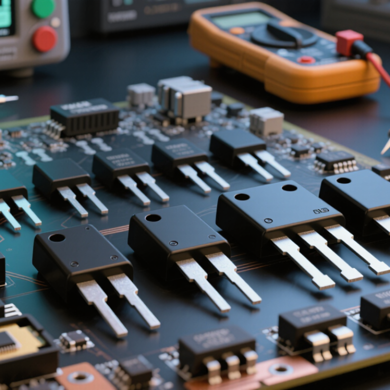
2026 Best Vishay MOSFET Replacement Options for Buyers

Understanding Vishay MOSFET Specifications and Replacement Requirements

Replacing a power MOSFET requires more than matching its voltage and current ratings. Start with the original circuit’s drain-source voltage, continuous current, pulse current, and maximum power loss. A replacement should provide suitable margin, not merely equal numbers. In a 48-volt motor controller, for example, a 60-volt device may face dangerous spikes during braking. A higher voltage rating can improve resilience, but it may increase resistance and conduction losses.

Check the on-resistance at the actual gate-drive voltage. A device rated at 10 volts may perform poorly with a 5-volt controller. Gate charge also affects switching speed, driver heating, and electromagnetic noise. Do not overlook the body-diode characteristics, reverse-recovery behavior, avalanche rating, and safe operating area. These details often decide whether a replacement survives repeated load cycles.

Package dimensions and pin arrangement must match the circuit board exactly. Thermal performance matters too. Measure the heatsink temperature after a realistic operating period, not only during a brief bench test. I have seen apparently suitable replacements fail because the copper area was too small. That mistake is easy to repeat. Compare datasheet test conditions carefully, since current ratings can reflect ideal cooling. Validate the candidate under startup, overload, and high-temperature conditions before approving production use. A small prototype test can reveal a costly assumption.

Matching Electrical Ratings for Safe MOSFET Substitution

Replacing a MOSFET safely starts with electrical ratings, not package appearance. The replacement should exceed the original drain-source voltage rating, especially where inductive spikes occur. A 600-volt device may fail quickly in a 500-volt switching circuit without sufficient transient margin. Check continuous drain current at the actual case temperature, not the headline value.

Thermal details matter just as much. Match RDS(on) at the intended gate voltage, because a lower value at 10 volts may perform poorly with a 4.5-volt driver. Compare total gate charge, switching losses, body-diode behavior, avalanche rating, and safe operating area. The package must also fit the board’s copper area and cooling path. Small differences become expensive.

The IEA’s Global EV Outlook 2024 reported more than 17 million electric cars sold worldwide in 2024, compared with about 14 million in 2023. That expanding power-electronics workload increases demand for dependable substitution decisions. However, market growth does not validate a casual cross-reference. I recheck datasheets, thermal impedance, and gate-drive waveforms before approval. A little humility helps. Lab testing can reveal ringing, unexpected heating, or slower turn-off that static ratings miss. For high-current designs, verify the full load profile, including startup, braking, short pulses, and fault recovery.

Comparing Package Types, Pinouts, and Thermal Characteristics

Choosing a 2026 MOSFET replacement requires more than matching voltage and current ratings. Package geometry often decides whether the design survives production. A 2024 Grand View Research report estimated the global power MOSFET market at approximately USD 10.5 billion in 2023, showing why replacement selection deserves careful engineering review.

TO-220 packages simplify hand assembly and provide accessible tabs for heatsinks. D2PAK packages save vertical space but depend heavily on copper area and board vias. DFN and QFN packages offer low inductance, yet their exposed pads require accurate stencil design and reflow control.

Fit matters. Pinouts may also differ, even within similar package outlines. Gate, drain, and source positions must be verified against the mechanical drawing, not only the symbol. A source-sense connection can improve switching accuracy, but it is easy to misroute.

Thermal performance needs measured conditions. Compare RθJC, RθJA, and transient thermal impedance using the same test assumptions. A 2024 Yole power semiconductor report highlighted continued growth in high-efficiency switching, where lower losses and higher power density increase thermal pressure.

Copper thickness, airflow, mounting torque, and interface material can change real temperatures substantially. Heat wins. A replacement with lower RDS(on) may still run hotter if its package dissipates heat poorly.

I have seen designs pass bench tests, then fail after enclosure assembly. That assumption fails. Datasheet values are useful, but infrared measurements and thermal-cycle testing reveal the uncomfortable gaps.

Evaluating Leading 2026 Vishay MOSFET Replacement Options

Evaluating Leading 2026 Vishay MOSFET Replacement Options requires more than matching voltage and package size. A 2025 Power MOSFET Market report projects steady demand growth through 2030, driven by electric vehicles, renewable energy, and compact power supplies. That trend increases pressure on buyers to verify supply stability and thermal performance.

A practical replacement should match drain-source voltage, continuous current, gate charge, RDS(on), and avalanche rating. Compare values at the same junction temperature. Datasheet figures can look attractive at 25°C, yet cooling conditions may change the result. Check the exact footprint, pin arrangement, and switching frequency before approving samples. Small differences matter.

For vehicle and industrial designs qualification evidence deserves close attention. A 2025 reliability analysis from a major power semiconductor research group highlights thermal cycling and package reliability as key selection concerns. Ask for production traceability, change-notification procedures, and test reports aligned with IEC or AEC requirements. Independent laboratory testing is useful when operating margins are narrow. It costs time.

Silicon superjunction devices can reduce conduction losses in high-voltage systems. Silicon carbide options may improve switching efficiency at elevated temperatures, but gate-drive design becomes more sensitive. That trade-off is easy to underestimate. I would test efficiency, electromagnetic noise, and temperature rise across light and full loads. One comparison at room temperature is not enough.

Selecting the Best Replacement for Performance, Cost, and Availability

Choosing a MOSFET replacement requires more than matching the original voltage and current ratings. In bench repairs, I compare drain-source voltage, continuous current, pulse current, and avalanche performance. The replacement must also fit the circuit’s gate-drive voltage. A low on-resistance value is attractive, but excessive gate charge can slow switching and increase driver losses. Check the package footprint, pin arrangement, thermal pad, and mounting space before ordering. Small details matter.

Tips: Build a short comparison table. Record voltage rating, on-resistance, gate charge, capacitance, package, price, and stock status. Ask distributors for current batch availability, not only catalog listings. Test a sample under realistic load, temperature, and switching frequency. Keep a second-source option ready.

Cost and availability often decide the final choice. A slightly more expensive device may reduce heat, simplify cooling, and improve long-term reliability. However, a premium specification can be wasteful in a low-frequency power stage. I once selected a very efficient part that performed poorly because its gate drive was too weak. That mistake looked obvious afterward. It was not obvious on paper. Use thermal calculations, then verify them with a temperature probe or infrared inspection. Review tolerances, production variation, and end-of-life notices where available. A replacement that works today may still create purchasing problems later.

2026 Best Vishay MOSFET Replacement Options for Buyers - Selecting the Best Replacement for Performance, Cost, and Availability

Replacement Option Typical Voltage Class Typical Continuous Current Range Typical On-Resistance at 10 V Gate Drive Typical Gate Charge Common Package Formats Best Use Case Performance Priority Relative Cost General Availability Critical Substitution Checks
Low-voltage power MOSFET 30–40 V 30–150 A 1–5 mΩ 20–100 nC TO-220, D2PAK, PowerSO-8, LFPAK Low-voltage DC-DC converters, battery protection, motor drives Very high Low High Drain-source rating, avalanche rating, thermal resistance, body-diode behavior, PCB land pattern
General-purpose 60 V MOSFET 60 V 20–120 A 2–10 mΩ 25–120 nC TO-220, D2PAK, PowerSO-8, TO-263 Automotive and industrial 12 V or 24 V power stages Very high Low High Automotive qualification where required, gate threshold, total gate charge, current derating, package pinout
80 V transient-tolerant MOSFET 80 V 15–100 A 3–15 mΩ 30–150 nC TO-220, D2PAK, PowerSO-8, LFPAK 24 V systems with switching overshoot and cable transients High Medium High Transient margin, unclamped inductive switching capability, reverse-recovery behavior, thermal headroom
100 V low-loss MOSFET 100 V 10–80 A 4–25 mΩ 35–180 nC TO-220, D2PAK, TO-263, PowerSO-8 48 V converters, telecom power, industrial motor controls High Medium High Voltage derating, switching frequency, gate-driver current, heatsink interface, drain-tab isolation
150 V rugged MOSFET 150 V 8–60 A 8–35 mΩ 40–220 nC TO-220, D2PAK, TO-247, PowerSO-8 High-voltage battery packs, industrial drives, isolated converters High Medium Medium Avalanche energy, insulation requirements, switching loss, safe operating area, mechanical clearance
200 V high-voltage MOSFET 200 V 5–40 A 15–60 mΩ 50–260 nC TO-220, TO-247, D2PAK High-voltage DC links, power-factor correction pre-stages, industrial supplies Medium–High Medium Medium DC-bus margin, creepage and clearance, turn-off overshoot, gate-loop layout, thermal impedance
600 V superjunction MOSFET 600–650 V 3–30 A 50–300 mΩ 20–180 nC TO-220, TO-247, D2PAK, SMD power packages Offline power supplies, PFC stages, lighting and appliance converters High at high voltage Medium High Switching frequency, diode reverse recovery, dv/dt immunity, creepage, controller gate-drive compatibility
650 V high-frequency MOSFET 650 V 2–25 A 80–500 mΩ 15–140 nC TO-220, TO-247, D2PAK, compact SMD packages High-frequency resonant converters and compact AC-DC equipment Very high Medium–High Medium–High Qg and Qgd, turn-on and turn-off losses, EMI behavior, thermal cycling, isolation distance
Automotive-qualified MOSFET class 40–100 V 20–150 A 1.5–20 mΩ 20–160 nC TO-220, D2PAK, PowerSO-8, LFPAK Automotive load switches, pumps, fans, electric power steering and battery systems Very high Medium–High Medium AEC-Q qualification, load-dump capability, short-circuit rating, humidity robustness, PPAP and traceability needs
Buyer guidance: The listed values are representative market ranges for comparable MOSFET classes, not guaranteed specifications for a specific device. Before approving a replacement, verify the exact drain-source voltage, continuous and pulsed current, on-resistance at the available gate voltage, total and Miller gate charge, body-diode characteristics, avalanche rating, safe operating area, thermal resistance, package dimensions, pin configuration, qualification requirements, and lifecycle status.

FAQS

What electrical ratings should be compared before replacing a power MOSFET?

Compare drain-source voltage, continuous current, pulse current, and maximum power loss. Choose ratings with practical margin, not identical numbers. A 60-volt device may face dangerous spikes in a 48-volt motor controller. Not always enough.

Why must on-resistance be checked at the actual gate-drive voltage?

On-resistance can rise sharply when the gate receives less voltage than specified. A device tested at 10 volts may perform poorly with a 5-volt controller. Check conduction loss at the real gate voltage and load current. Paper values can mislead.

How does gate charge affect switching performance?

Higher gate charge can slow switching, heat the driver, and increase electrical losses. It may also create more electromagnetic noise. Review turn-on and turn-off waveforms at the intended switching frequency. A weak driver once made an efficient device perform badly.

What thermal checks are needed before approving a replacement?

Measure heatsink or case temperature after realistic operating time. Do not rely on a brief bench test. Check copper area, thermal pads, thermal impedance, and airflow. Use a temperature probe or infrared inspection during full load. Small copper areas can fail.

Can a MOSFET with matching ratings fit any circuit board?

No. Package dimensions, pin arrangement, thermal pad, and mounting space must match exactly. Confirm drain, source, and gate orientation before soldering. A similar outline can hide reversed pins.

Which less obvious specifications can determine replacement reliability?

Check body-diode behavior, reverse-recovery performance, avalanche rating, and safe operating area. These details matter during braking, inductive switching, and repeated load cycles. Static ratings do not tell the whole story.

How should a candidate replacement be tested?

Test startup, overload, short pulses, braking, fault recovery, and high-temperature operation. Observe ringing, turn-off speed, current sharing, and temperature rise. A brief bench test is insufficient. Ringing can appear later.

How should cost and availability influence the final selection?

Compare price, current stock, production variation, and future supply notices. Record voltage, resistance, gate charge, capacitance, package, and stock status in a small table. A slightly costlier device may reduce heat and cooling requirements. Keep a second-source option ready.

Is the highest-rated replacement always the best choice?

No. Excessive voltage or current capability can increase cost, resistance, or gate charge. A premium specification may be wasteful in a low-frequency power stage. The best choice balances electrical margin, thermal behavior, switching needs, and supply stability. I still recheck the calculations.

Conclusion

Choosing the right Vishay Mosfet Replacement in 2026 requires more than comparing product names or prices. Buyers should first understand the original device’s voltage, current, resistance, gate-charge, switching-speed, and power-dissipation requirements. A suitable substitute must meet or exceed critical electrical ratings while remaining compatible with the circuit’s operating conditions. Careful attention should also be given to package dimensions, pin configuration, thermal resistance, mounting method, and cooling capacity, since physical or thermal mismatches can lead to instability or premature failure.

The best replacement options should be evaluated across performance, efficiency, cost, and supply availability. Devices with lower conduction and switching losses may improve system efficiency, while robust thermal characteristics can support greater reliability in demanding applications. Buyers should confirm datasheet specifications, test the replacement under realistic load conditions, and consider long-term sourcing stability before making a final decision. This balanced approach helps identify a dependable and cost-effective solution without compromising electrical safety or system performance.


Isabella

Isabella

Isabella is a dedicated marketing professional with a sharp focus on driving brand growth and engagement through strategic content creation. With an extensive background in digital marketing, she combines her passion for storytelling with her keen understanding of industry trends to deliver......